Writing Quality
12. EFM - Page 2
Review Pages
2. Pits and Lands
3. Error Correction - Page 1
4. Error Correction - Page 2
5. Error Correction - Page 3
6. CIRC - Page 1
7. CIRC - Page 2
8. CD Decoding system
9. C1/C2 Errors - Page 1
10. C1/C2 Errors - Page 2
11. EFM - Page 1
12. EFM - Page 2
13. Jitter - Page 1
14. Jitter - Page 2
15. Jitter - Page 3
16. Oscilloscope
17. Jitter at DVD
18. Technologies for Reducing Jitter
19. JVC ENC K2
20. AudioMASTER
21. VariREC
22. TEAC Boost Function
23. Testing Equipement - Page 1
24. Testing Equipement - Page 2
25. Calibration media
26. Tests before recording
27. Tests after recording
28. Atomic Force Microscopy
Writing Quality - Page 12
EFM - Page 2
- RF Signal
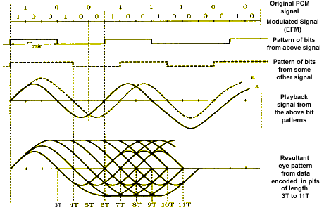
The RF signal from the disc contains all data, and is also used to maintain proper CLV rotation velocity of the disc. 3T describes a 720 KHz signal, and 11T describes a 196 KHz signal at 1.2 m/s. T refers to the period of 1 channel bit which is 464 ns. A collection of EFM waveforms is called the "eye pattern". Whenever a player is tracking data, the quality of the signal can be observed from the pattern.
Below we can see a picture of showing the various stages from the original PCM signal up the eye pattern. The modulated EFM signal is read from the disc as a RF signal. The RF signal can be monitored through an eye pattern by simultaneously displaying successive waveform transitions.
- Demodulation
During the demodulation, the "eye pattern" from disc is converted to NRZI (Non Return to Zero Inverted) data coding, then is converted to NRZ then to EFM data and finally to the Audio data. Following demodulation, data is sent to a Cross-Interleave Reed-Solomon code circuit for error detection and correction.

Eye Pattern
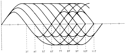
The eight-to-fourteen (EFM) modulation scheme used produces just nine different possible lengths of pits and lands. Therefore, the resulting HF consists of square waves of nine different durations. The signal appears sinusoidal on the 'scope because of the limited frequency response of the optics. It is common to display the photo detector output on a scope with a conventional trigger.
This results in a display where the nine possible frequencies (3T to 11T) all add up on top of each other. This type of display is termed an "eye pattern" and provides valuable information about the various alignment parameters of the CD player. Notice that the relationship between size and wavelength is very distinct in the eye pattern.
The RF output is converted to a square wave, and then phase locks a clock with the period T. Each of the nine pit/land lengths are exact multiples of one fundamental length, called 1T.
The T represents the data clock period, which is 231 nanoseconds at 1X read speed. The particular run length is referenced by nT where n is an integer multiple of the clock period. The nine possible lengths of pits and lands are 3T, 4T, 5T, 6T, 7T, 8T, 9T, 10T, and 11T. The waveforms generated by these pits & lands are called I3, I4, I5, I6, I7, I8, I9, I10 and I11 respectively. I3 represents the shortest pit / land, and I11 represents the longest pit or land.
Review Pages
2. Pits and Lands
3. Error Correction - Page 1
4. Error Correction - Page 2
5. Error Correction - Page 3
6. CIRC - Page 1
7. CIRC - Page 2
8. CD Decoding system
9. C1/C2 Errors - Page 1
10. C1/C2 Errors - Page 2
11. EFM - Page 1
12. EFM - Page 2
13. Jitter - Page 1
14. Jitter - Page 2
15. Jitter - Page 3
16. Oscilloscope
17. Jitter at DVD
18. Technologies for Reducing Jitter
19. JVC ENC K2
20. AudioMASTER
21. VariREC
22. TEAC Boost Function
23. Testing Equipement - Page 1
24. Testing Equipement - Page 2
25. Calibration media
26. Tests before recording
27. Tests after recording
28. Atomic Force Microscopy