Blu-Ray Writing Quality Tests
3. Basic Blu-Ray Disc Writing Quality Signals
Review Pages
2. Specs, Modulation, Error Correction On Blu-Ray
3. Basic Blu-Ray Disc Writing Quality Signals
4. Testing procedure - The DaTARIUS dataBANK
5. Measurements - LG GBW-H10N 2x & Memorex BD-R
6. Measurements - LG GBW-H10N 4x & TDK BD-R
7. Measurements - LG GBW-H10N 4x & Verbatim BD-R
8. Measurements - LG GBW-H10N 2x & TDK BD-RE
9. Measurements - LG GBW-H10N 2x & Verbatim BD-RE
10. Measurements - LG GBW-H10N 2x & Sony BD-RE
11. Measurements - LiteOn LH-2B1S 2x & Memorex BD-R
12. Measurements - LiteOn LH-2B1S 2x & TDK BD-R
13. Measurements - LiteOn LH-2B1S 2x & Verbatim BD-RE
14. Measurements - LiteOn LH-2B1S 2x & Sony BD-RE
15. Measurements - LiteOn LH-2B1S 2x & TDK BD-RE
16. Measurements - Plextor PX-B900A 2x & Verbatim BD-R
17. Measurements - Plextor PX-B900A 2x & TDK BD-R
18. Measurements - Plextor PX-B900A 2x & Verbatim BD-RE
19. Summary
The measurement issues for the next generation formats, go substantially beyond simply working with smaller features. The coding concepts, the relationships between measurements and playability are all unique.
Let's start with the basic signals related to the measurements for the Blu-Ray disc, as they are provided by the Blu-Ray specifications.
References:
BD Specifications for Read-Only Disc
Part 1 Physical Specifications
DaTARIUS BD Signal Guide v1.0
Blu-Ray Signals |
|||
| Abbreviation | Specification | ||
| Mechanical parameters | |||
| Focus Error 1 - Axial residual error | FE1 | ≤ 45 nm | |
| Focus Error 2 - The rms noise of axial residual error |
FE2 | ≤ 75 μmpp | |
| RADIAL1 - Radial residual error | RADIAL1 | ≤ 9 nm | |
| RADIAL2 – The rms noise of radial residual error |
RADIAL2 | ≤ 6.4 nm BD SL ≤ 9.2 nm BD DL |
|
| Optical Parameters | |||
| I8H– Reflectivity in recorded tracks | BD R8h-rth | Min 35 % Max 70 % |
|
| BD R8h-rth | Min 12 % Max 28 % |
||
| Track pitch | Tpwa - TRP averaged over the Wide Pitch area | 0.350 ±0.003 μm | |
| Tpna - Track pitch averaged over the Normal Pitch area | 0.320 ±0.003 μm | ||
| Operating Signals | |||
| 8T peak to peak modulation | I8/I8H | ≥ 0.40 | |
| 3T peak to peak modulation | I3/I8 | ≥ 0.25 |
|
| Resolution I2/I8 equalized | I2/I8 | ≥ 0.09 BD SL ≥ 0.09 BD DL |
|
| 8T modulation variation within one revolution | I8HRv | ≤ 0.15 | |
| Reflectivity modulation | R8M | Min 0.20 Max 0.70 |
BD SL |
Min 0.07 Max 0.28 |
BD DL | ||
| Asymmetry | Asym | Min 0.10 Max 0.15 |
|
| Leading edge jitter applying Limit Equalizer | JRLi | ≤6.5 % | |
| Trailing edge jitter applying Limit Equalizer | JFli | ≤6.5 % | |
| Radial Push Pull | RPP | Min 0.10 Max 0.35 |
|
| Track crossing signal | TCS | ≥ 0.10 | |
| Differential Phase Detection – signal amplitude |
DPDAMp | Min 0.28 Max 0.62 |
|
| Differential Phase Detection – signal amplitude |
DPDAsy | ≤ 0.20 | |
| Digital errors | |||
| Burst Error Count | BEC | In each physical cluster BEC: the number of burst error with a length ≥ 40 bytes shall be less than 8 |
|
| Burst Error Length | BEL | In each physical cluster BEL: the sum of all burst error length shall be equal or below 600 bytes |
|
| Symbol Error Rate | SER/SERk | ||
| Random Symbol Error Rate | RSER/RSERk | ≤ 2.0 * 10-4 | |
Below is a brief explanation of the basic signals related to the BD quality measurements. These signals are the RSER, BEC,
R8H,
I8/I8H,
RADIAL2,
JFLi and
JRLi.
Digital Errors
For BD, signals related to digital errors are Random Symbol Error Rate (RSER), Burst Error Max, and Max total length of burst errors.
- RSER / RSERk– Random Symbol Error Rate

The Random Symbol Error Rate is defined as the Symbol Error Rate where all erroneous bytes contained in burst errors of which the length is ≥ 40 bytes are excluded from counting in the numerator as well in the denominator of the SER calculation.
The RSER value is calculated over 10,000 LDC Blocks. We should remind here that Long Distance Code (LDC) is included to protect the data. For more information read the previous page of this article.
Such errors can be caused by all optical defects that interfere with the normal data read-out procedure (scratches, dots, black spots, bubbles, etc). Local defects can cause the data contents to deteriorate. Others causes can be jitter problems, stamper defects or a bad HF signal.
- BEC – Burst Error Count
A byte error is when one or more bits (inside a byte) have a wrong value (as detected by the error correction/detection circuits).
A burst error is a sequence of bytes in which there are not more than two bytes between any two erroneous bytes. In order to determine the burst errors, the bytes should be ordered in the same sequence as they are recorded on the disc. The length of the burst is defined as the total number of bytes counted from the first erroneous byte that is separated by at least three correct bytes from the last succeeding erroneous byte.
The number of erroneous bytes in a burst is defined as the actual number of bytes in that burst that are not correct.

As in the case of RSER, such errors can be caused by all optical defects that interfere with the normal data read-out procedure (scratches, dots, black spots, bubbles, etc).
Operation signals
I8H– Reflectivity in recorded tracks
The reflectivity parameter is the measure of the fraction of the light returning from recorded layer in the information zone. It should include also transmission through the cover layer. There are two types of discs foreseen: higher reflectivity and lower reflectivity type.
Measuring conditions are specified. There are two preferential methods:
- collimated (parallel) beam method
- focused beam method
The focused method is used in players together with a reference disc of known reflectivity value. The method is relative, yet it allows to eliminate the light from parasitic reflectance's inside the disc as well as the light coming from the front surface of the cover layer as well.
In the collimated method "total" reflectance is measured, and a calculation is needed to determine the reflectance from the information layer. For this method a very good reference disc (birefringence-free), with glass cover layer, and golden reflective layer should be chosen.
Reflection is basically defined by the reflective layer. In most cases during the manufacturing process of Blu-Ray media, out-of spec
reflectivity means correction on the sputtering process (reflective layer
application). In some case this can be also connected with wrong dimensions
of the pits in the information area, or scattering of light on the surface of the
cover layer.
I8/I8H – 8T peak to peak modulation
In the reading process of a BD disc, the HF signal is obtained by summing the currents of the four elements of the photo detector. Below you can see an illustration of an HF signal.

8T Modulation shall be calculated according to the formula:

The value of I8/I8H modulation reveals information about the shape of the pits, and subsequently of the quality of the replication process. A value lower than the limit will lead to higher error rates and jitter.
Jitter on Blu-Ray
Assessing the quality of HD DVD and BD discs introduces new approaches to those accepted for DVD and CD and we look here at jitter, the most commonly understood quality metric.
Jitter, the difference between the idealized run lengths (pit and lands) and the actual detected run lengths, has been used in CD and DVD as a primary metric for determining the quality of the replicated disc.
When using a PRML approach, it has not been able to link regular (as used in CD and DVD) jitter directly to the quality of the replicated disc.
BD uses a different approach. In BD, a limit equalizer is employed upon the signal. This is simply another method of boosting the signal of the smallest features (2T pit and land). The advantage of the limit equalizer, compared with the conventional equalizer used for DVD, is that it can boost the signal of the smallest features without increasing the InterSymbol Interference (ISI). After the signal has been processed through the limit equalizer, jitter measured in a conventional manner, as with DVD.
According to the Blu-Ray specifications, two signals have been defined for jitter measurements:
JRLi – Leading edge jitter applying Limit Equalizer
JFLi – Trailing edge jitter applying Limit Equalizer
Both leading and trailing edge jitters should be measured in each track with the use of circuit corresponding to the following drawing. These jitters are data-to-clock jitters measured with the Limit Equalizer set appropriately to Channel bit length.

The jitter value expresses the distribution of rising or falling edge positions for all the pits on a disc. In other words, jitter is the standard deviation of the falling and rising edge of the digitized and equalized HF signals in respect to the PLL clock.
The limits in jitter are the same for the leading as for the trailing edge of the pits. However, there are small differences in the specifications of jitter for dual layer discs. Higher jitter is in layer 1 is allowed when it is measured together with I2 pits ( ≤ 8.5%). Without the I2 the limiting value of the jitters are always the same ( ≤ 6.5%).
Jitters indicate accuracy in the definition of pits on a discs, and is likely to be a influenced by the moulding process. Further reasons be an overly low HF signal, due to low reflectivity of the reflective layer. If these process steps are ruled our then the stamper, and possibly even the mastering process, must be checked.
Servo &Tracking parameters
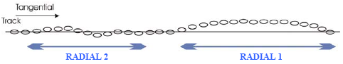
RADIAL1 – Radial residual error
The parameter, similarly to Focus Error, imposes limits on movements of the
head due to residual radial tracking error to 9 nm (for frequencies below 1.8
kHz). Spikes in the residual radial tracking error signal due to local defects,
such as dust and scratches, are excluded.
For dual layer discs the value of 13 nm is allowed.
The parameter protects the head from losing a track during reading due to any
extreme displacement of the track in a radial direction. This means that for
frequencies below 1.8 kHz the maximum local acceleration of the tracks in the
radial direction will not exceed 1.5 m/s².
For dual layer discs the value of 2.2 m/s² is allowed.
RADIAL2 – The rms noise of radial residual error
This is related to rms (root mean square): in other words the average value of
the RADIAL1 signal. The value should be lower than 6.4 nm, when measured
in the frequency band 1.8 kHz to 10 kHz, with integration time of 20 ms, and
using the reference servo for axial tracking.
For Dual Layer discs the value 9.2 nm is allowed.
Leaving behind all the theoretical aspects related to the Blu-Ray measurements, in the following pages we present the writing quality measurements we have carried out, in cooperation with DaTARIUS.
Review Pages
2. Specs, Modulation, Error Correction On Blu-Ray
3. Basic Blu-Ray Disc Writing Quality Signals
4. Testing procedure - The DaTARIUS dataBANK
5. Measurements - LG GBW-H10N 2x & Memorex BD-R
6. Measurements - LG GBW-H10N 4x & TDK BD-R
7. Measurements - LG GBW-H10N 4x & Verbatim BD-R
8. Measurements - LG GBW-H10N 2x & TDK BD-RE
9. Measurements - LG GBW-H10N 2x & Verbatim BD-RE
10. Measurements - LG GBW-H10N 2x & Sony BD-RE
11. Measurements - LiteOn LH-2B1S 2x & Memorex BD-R
12. Measurements - LiteOn LH-2B1S 2x & TDK BD-R
13. Measurements - LiteOn LH-2B1S 2x & Verbatim BD-RE
14. Measurements - LiteOn LH-2B1S 2x & Sony BD-RE
15. Measurements - LiteOn LH-2B1S 2x & TDK BD-RE
16. Measurements - Plextor PX-B900A 2x & Verbatim BD-R
17. Measurements - Plextor PX-B900A 2x & TDK BD-R
18. Measurements - Plextor PX-B900A 2x & Verbatim BD-RE
19. Summary