PC POWER COOLING Silencer MKIII 750W review
3. Cables, PCB
The power supply utilizes a single 12V rail design to deliver most of the power for the unit. It can supply up to 62A at 12 V, almost its entire capacity (744 watts), at this voltage. The minor rails have 120W maximum combined output, which will cover all the needs of a modern system, and the 3A maximum that the 5VSB can output will suffice in most cases.
The maximum combined output of the PSU is 750 watts:

| PC Power & Cooling Silencer MK III 750 Power | |||||||
|---|---|---|---|---|---|---|---|
| Rail | 3.3V | 5V | 12V | 5VSB | -12V | ||
| Max. Power | 24A | 24A | 62A | 3A | 0.5A | ||
| 120W | 744W | 15W | 6W | ||||
| Total Max. Power | 750W | ||||||
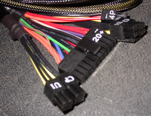
The Silencer Mk III provides plenty of cables and connectors:
| Native Cables | |
|---|---|
ATX connector (625mm) |
20+4 pin |
4+4 pin EPS12V/ATX12V (640mm) |
2 |
| Modular Cables | |
6+2 pin PCIe (580mm) |
4 |
SATA (400mm+150mm+150mm+150mm) |
12 |
4 pin Molex (400mm+150mm+150mm+150mm) |
4 |
FDD adapter (+100mm) |
1 |

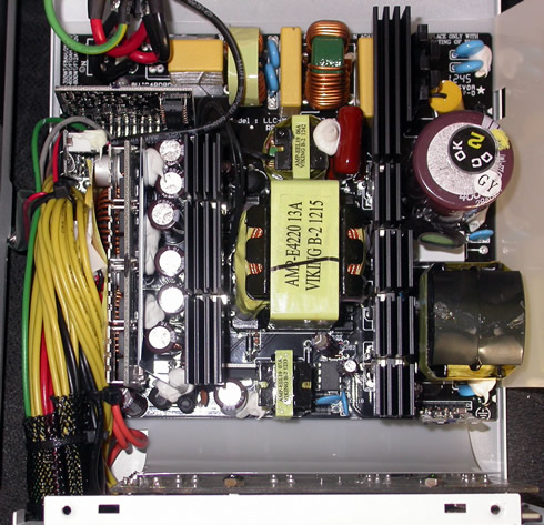
Below you see a picture of the internal of the PSU:
The components and their arrangement on the PCB contribute to an overall clean layout.
The MK3S750 is based on a half-bridge topology along with an LLC resonant converter for added efficiency. The secondary part of the main transformer includes a synchronous rectification circuit along with two VRMs for the generation of the minor rails.
As you see in the picture above, a pair of heatsinks run the length of the unit and separate the three main sections of the PSU: 1) the Active PFC (APFC) section (right side), which is actually a AC/DC converter controls the current supplied to the PSU so that the current waveform is proportional to the mains voltage waveform; 2) the transformer section (middle), which isolates primary from secondary side and converts (steps down) the voltage which feeds the secondary rectifiers that generate all DC outputs (+12V, 5V, 3.3V, 5VSB, -12V) and; 3) the output rectifiers and filters (left side) , which rectify and filter the high frequency switching waveform created by the MOSFETs and fed through the secondary of the main transformer.
In the APFC section, two Infineon fets chop the incoming rectified DC signal, a CREE C3D08060A boost diode and the PFC controller (NCP1653 IC). A hold up cap is provided by Nippon Chemi-Con having 560 μF capacity. The capacitor is rated at 105°C, 400V, KMQ series. There is also a thermistor responsible for protection against large currents and the relay that bypasses it once the start-up phase finishes.
On the secondary side, the +12V rail is generated using four IPP041N04N fets. All caps of the secondary side are provided by Nippon Chemi-Con and are rated at 105°C.
Where appropriate components are given extra stability by white adhesive and wiring it tied in place and plastic separators.

