1.3GB Fujitsu Magneto-Optical MCE 3130 AP and SS
7. Appendix II. MSR technology details
Appendix II. MSR technology details
The following picture shows the exactly how the magnetic mask mechanism is implemented on the various media layers.
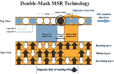
The Reading and Middle layer have different temperature distributions (from low to high) relative to the elapsed time, as the laser beam, due to the disk rotation, comes over a particular bit of the disk and is irradiated.
In the part of the disk where the temperature is low, the magnetization of the particles in the middle layer is directed in parallel to the externally applied field. Subsequently, the particles in the reading layer are set to the same orientation regardless of the orientation of the recording layer. Thus a front mask is created as shown at black spot on the side picture.
In the part of the disk where temperature is high, because of the fact that the particles in the middle layer have been heated at a temperature higher that that of Curie point, the magnetization is lost. Consequently, at of the reading layer each particle is magnetized in the direction of the applied magnetic field. This creates a rear mask, the white spot in the picture.
Only a part of the disk in the middle layer characterizes the direction at which the recording layers are magnetized. This allows an easy distinction of the polarization of the data bits and easily enables the drives electronics to recover the recorded data.
The gain of recording density is clearly shown in the picture below, where you can see the read out (analog) signal differences between MSR and normal MO reading.
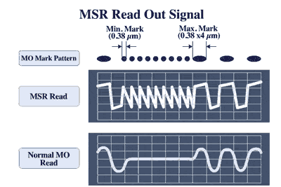
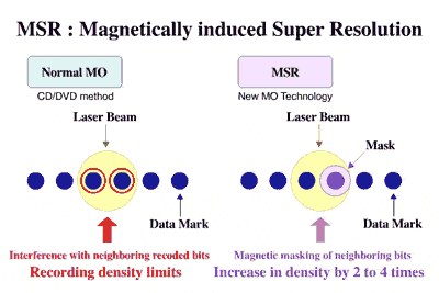
In short, MSR Technology aims to reduce the interference among neighboring recorded bits (intersymbol interference). Magnetic interference is a phenomenon by which suffer not only MO but pure magnetic media as well. In our case it emerges when reading from two or more consecutive polarized spots (bits). Intersymbol interference limits the attainable recording density. As it can be seen in the relative graph, MSR encloses each spot in a magnetic mask creating an appropriate magnetic isolation which enables an easier detection of the relative peaks in the analog waveform readout. According to Fujitsu, the application of the MSR technology can increase the recording density by 2 to 4 times.
The table below lists major characteristic values of the relevant specifications for each MO media type.
| Disk Capacities | ||||
|
128MB |
230MB |
540MB |
640MB |
|
|
Track pitch [micro-m] |
1.60 |
1.39 |
1.10 |
1.10 |
|
Modulation |
RLL2-7 |
RLL2-7 |
RLL1-7 |
RLL1-7 |
|
Sector length [bytes/sector] |
512 |
512 |
512 |
2048 |
|
Linear density [micro-m/byte] |
8.7 to 13.7 |
7.1 |
4.0 |
4.0 |
|
Bit transfer rate [M Bit/Sec] |
21.8 |
26.1 to 41.8 |
35.0 to 58.8 |
34.9 to 58.1 |
|
Maximum frequency of data |
7.25MHz |
13.92MHz |
14.71MHz |
14.54MHz |
From the above table we can see that while since mid 90's all hard disks employ PRML (partial response, maximum likelihood) encoding schemes, all MO drives (up to those tested here) employ pure peak detection (RLL).
The newer 2.6GB, 5.2GB and 9.1GB disk formats will be encoded under a PRML scheme. Perhaps part of the reason that these larger capacity disks will be attainable might be the employment of this newer encoding technology.
Unfortunately, unlike the CD and DVD format cases, where there is abundance of available technical information to the public, in the case of MO recording we were unable to obtain the necessary technical information. It seems that the MO disk alliance wants it to be this way:)


