Introduction to 3D graphics
Most of us have played a 3D game before, be it on a PC, a game console or other gaming devices. However, most of us don’t really know how a 3D scene is created, and you certainly don’t have to know it in order to enjoy playing 3D games.
If you want to know it, for whatever reasons, this article should give you a bit of an introduction to 3D graphics.
If we compare 3D graphics with the real world, the real world has the advantage of being infinite in size and detail, down to the atoms that make up molecules that make up materials that make up objects and so on and so forth. Obviously, computing devices can only store and process a limited amount of data. So when attempting to model the real world, shortcuts need to be taken and if you look closely enough at any digitized picture, you will see flaws that are not visible in the real world.
In order to maximise the level of detail while minimising the amount of data to be stored and processed, the world is broken down into a set of objects which make up the 3D scene. These objects are then broken down into a set of building blocks that are known as primitives. The most used 3D primitives are polygons whose shape is defined by 3 or more vertices, also known as polygon primitive. In today’s 3D world, the most used polygon primitive is the triangle, defined by the minimum number of vertices, i.e. 3.

Virtually any shape can be created joining multiple triangles together at their vertices

Generally, the more triangles are used for an object, the more detailed it can be modelled by the 3D artist. The drawback is that the more triangles are used, the more computational power is required to create this object. In the past, the CPU was responsible for the calculation of this so called object geometry. This changed when Microsoft DirectX 7 and the graphics chips capable of it introduced the possibility of having geometry calculated on the graphic chip, rather than on the CPU. However, the capabilities of this fixed function geometry engine, also referred to as T&L engine (Transform and Lighting) were limited and thus only represented the first step into what is now known as Vertex Shader engines introduced with DirectX 8.
Today’s geometry engines are called Vertex Shaders because they are programmable and can run so called (vertex) shader programs to calculate and animate the geometry of a scene. Every vertex that needs to be calculated can contain a great deal of information, such as an x,y,z coordinate (a 3-dimensional position), texture coordinates, Normal Information (what direction the vertex faces), an identifier (which triangle it belongs to), Skinning parameters, lighting values or just about anything else.
 |
| Picture 3: Triangles made visible in a scene of ATI’s Ruby demo. |
But vertex processing alone does not result in a visible picture. In order to see all the triangles made up of all the vertices that the vertex shaders have calculated, they need to be coloured.
In simple terms, the invisible object that is a result of the geometry processing needs to be “wallpapered” so it becomes visible.
To be able to do this, the polygons need to be converted into pixels; this is done during the triangle setup. The pixels are then dealt with in the pixel shaders and pixel pipelines.
The colour value of a pixel is looked up on a texture; this texture resides in graphics memory as a bitmap that was designed by the 3D artist. Textures can be available in different resolutions. Higher resolution textures look better, but consume more memory space and more memory bandwidth than lower resolution textures. For far away objects, this would not only result in wasted processing cycles, it could also lead to display anomalies. Because of this, textures are usually available in different resolutions. If textures of different resolutions are combined on one object (for example a path that stretches from the front to the back of the picture) then this is referred to as mip-mapping. This mip-mapping can lead to visible borders between the two textures of different resolutions, called mip-map banding. And this mip-map banding can be minimised using different filtering techniques.
Filtering means that for every pixel to be coloured, more than one texel on the texture is looked up and the average is calculated and applied to the pixel. Point Sampling only looks up one texel, Bilinear Filtering looks up four texels, Trilinear Filtering looks up 8 texels (4 on the first mipmap level and 4 on the second mipmap level) and Anisotropic Filtering uses up to 128 texels to create just one pixel (when using 16x Anisotropic Filtering).
 |
| Picture 4: How different filtering techniques work, from Point Sampling to 2x Anisotropic Filtering. Click to see the details. |
So we got our colour values in form of texels, we filtered them and we apply them to get a coloured pixel. Is that it?
Far from it, there is a lot more that can be done on the pixel level. For example, several textures can be combined in order to create special effects. But most important, let’s not forget what can be done in the Pixel Shaders.
Like Vertex Shaders, Pixel Shaders are programmable units in the chip that can run mathematical algorithms in order to create special effects. A special effect in this case can mean anything, per pixel lighting calculations, material properties that determine how strong and into what direction light is reflected, bumpmapping effects that add the visual impression of a structure to a flat surface, procedural textures (which are textures that don’t rely on a bitmap but are calculated) and many more.
The programmability and power of modern Pixel Shaders allows game developers to be more creative than ever before, creating more special effects that add more realism to games.
Pixel Shaders were introduced with DirectX 8, but their major breakthrough came with DirectX 9. Not only are DirectX 9 Pixel Shaders more flexible and efficient than predecessors, the introduction of the High Level Shading Language (HLSL) allowed developers to program them using a C-like programming language which accelerated their adoption. In addition to that, DirectX 9 also introduced floating point accuracy, making effects like High Dynamic Range (HDR) possible.
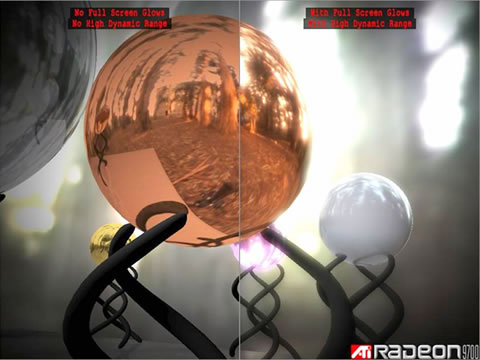 |
| Picture 5: Comparison screenshot showing the effects of HDR in ATI’s “Rendering with Natural Light” demo. |
But there is more. Depending on the screen resolution you are running at, you may see jaggies (steps) along the border of objects, this is what we call Aliasing. To combat the Aliasing effect, we use a technology that we call (you guessed it) Anti-Aliasing.
Essentially, Anti-Aliasing works by taking multiple samples of an image and then calculating the average of these samples. And as always, the more samples you take, the better the quality but the higher the performance hit. There are different approaches to Anti-Aliasing which determine how these samples are taken, and the most commonly used one is Multi-Sample Anti-Aliasing (MSAA), which again comes in different flavours (different sampling patterns, gamma corrected AA etc.).
| 0xAA |  |
| 2xAA |  |
| 4xAA |  |
| 6xAA |  |
| Picture 6: Anti-Aliasing from no AA to 6xAA. | |
At the end of the pixel pipeline, we write the data out into the frame buffer, which is a dedicated amount of memory to which the frames are written into. Once a frame buffer is full, i.e. the picture is complete, it will be sent to the monitor. And there you have it, properly calculated object geometry, textured, filtered, full with special effects, proper light calculations and AA applied, visible for a split part of a second, until the next frame arrives which went through the same process.

By Rene Froeleke
ATI Technical PR Manager