Foxconn Rattler P67 review (Quantum Force)
2. package, closer look
Review Pages
The Foxconn Rattler retails for about €165~175, a reasonable price for a P67 motherboard.
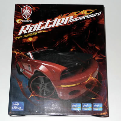
In the picture below you see the retail package of the board. The red sports car on the front side of the box looks aggressive surrounded by flames and shows Foxconn's intention to deliver a high-performance motherboard.
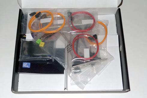
The provided accessories include:
- User's manual
- 2 x SATA 3.0Gb/s cables
- 2 x SATA 6.0Gb/s cables
- 1x IDE cable
- 1x USB2.0 back panel slot card
- 1 x Back-Panel
- 2x power molex to SATA cables
- 1x CD with drivers
As you see in the picture below, the board has a clear layout with basic slots and ports painted in red. Quantum Force has been used to creating visual sensation by matching the color with black and red:

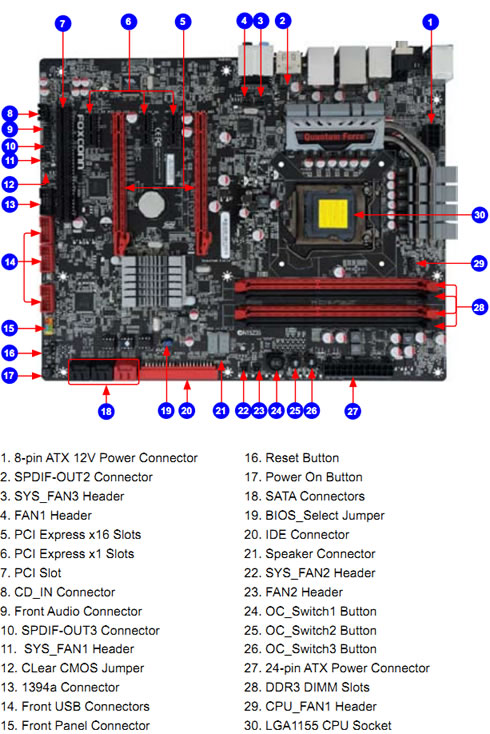
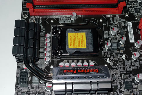
The 12-phase power and aggressive looking heat sinks absorb heat around the CPU area. CPU power supply uses 14 phase Hybrid PWM which can parallel connection at the same time. The extra 2 phases are available for both the VTT and the Memory power. The free space around the CPU socket is enough to allow for easy installations of large CPU heat sinks.
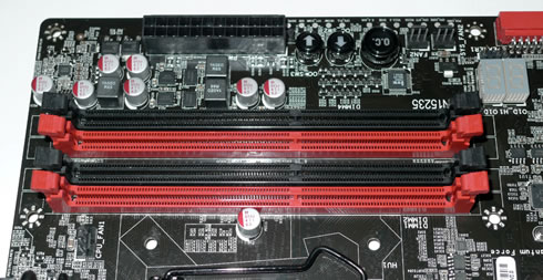
There board provides four (4) memory DIMM slots capable of up to 16GB of DDR3 rated at 1066MHz all the way up to 2133MHz (OC). However, XMP is not profile supported, meaning that you'll have to manually set speed/timings during overclocking.
Close to the memory slots there are three buttons used for overclocking: An OC button as well as an up and down arrow for adjusting the BCLK on the CPU. However, Sandy Bridge BCLK should remain at 100MHz and the multiplier should only be altered to adjust CPU clock speed. These buttons could be very useful if they could adjust the multiplier instead.
There are also two a diagnostic 7-segment display, which mainly displays error codes. Looking at the motherboards manual will not help you identify the meaning of these error codes.
Pressing the OC button whilst the system is booted will cause all 3 buttons to illuminate. The LED indicator to the left will then signal "00" (100 BCLK) and pressing the up button will cause the LED to display 0.1 meaning 101 BCLK. Pressing down the down arrow does the reverse.
Finally below the buttons there are voltage measuring points.
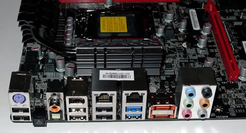
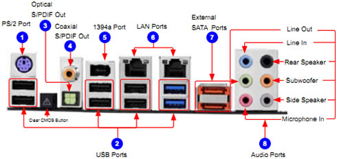
The I/O panel area includes:
- 1 x PS/2 keyboard port
- 1 x S/PDIF out Optical port
- 1 x S/PDIF out Coaxial port
- 2 x USB 3.0 ports
- 1 x 1394 port
- 1 x Audio jack supports 6 jacks
- 2 x RJ45 LAN ports
- 2 x eSATA ports
- 6 x USB 2.0 ports
- 1 x CCMOS Button
The motherboard supports 2 x PCIe 2.0 x16 (single at x16 or dual at x8/x8 mode), 3 x PCIe 2.0 x1 and one PCI port. The PCIe 2.0 x16 ports are properly positioned on the board to accommodate multi-GPU setups.

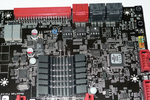
At the upper right area there are 2 x SATA 6.0 Gb/s (red) and 4 x SATA 3Gb/s ports (black) based on the Intel P67 chipset. There are also two very handy power and reset buttons. Surprisingly, there is also an IDE port there, useful for all those who still use IDE HDD. We would prefer to see two additional SATA ports there instead:
At the bottom of the Rattler motherboard are 3 x USB2.0 headers. These give you up to 8 x USB2.0 ports. Combined with the I/O we have up to 12 x USB2.0 available.
Other internal I/O connectors and ports found on the panel:
1x ATX 24-Pin power connector.
1x 8-pin ATX 12V power connector.
1x 4-pin CPU Fan connector
3x 3-pin System Fan connectors .
2x 3-pin System FAN(no FAN control)
1x Front panel header
1x Front Audio header
1x CD-IN
1x CLR_CMOS
2 x Onboard Debug LED ports
3 x USB 2.0 connectors support additional 6 ports
3 x New LED Button for Quick Power/ Reset/ CCMOS
4 x SATAII connectors
2 x SATAIII connectors
1x IEEE1394a header
1x SPDIF OUT
1 x IDE connector
1x Speaker header
Review Pages


