MSI 915G Combo
2. CPU & Cooler
02 - Board Layout
CPU & Cooler
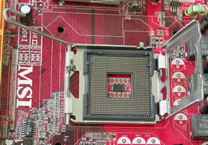
In the socket 775 architecture, the pins have moved from the processor on to the motherboard's socket. That way, breaking one of them no longer results in a destroyed processor but a destroyed motherboard which could be replaced using the RMA service (depending on the manufacturer).

Inside the 915G Combo package, you will find a plastic CPU clip for installing the CPU without damaging the socket pins. You are supposed to clip it on the CPU by pushing it on it and then unclip it by "pushing the CPU down hard" just as MSI suggests in the accompanying install guide. We found it really inconvenient to install the CPU that way, as we wasted about 3 minutes to get it right and finally decided to place it on the socket by hand which is far easier and in our opinion much safer (just make sure you ground yourself first to discharge any static electricity).
The rest of the operation was a breeze, as you just have to make sure the CPU is seated well into the socket, cover it with the metal plate and pull down the lock/release lever to secure the CPU.
Memory Modules
The memory banks are probably the most interesting part of the motherboard. If you take a good look at the following picture, you'll notice apart from the colors, that there are two different types of slots. The 2 orange slots are for use with 240-pin DDR2 DIMM and the 2 light green ones for the 184-pin DDR DIMM.
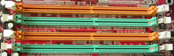
Since DDR2 is not backwards compatible you'll notice that the small notch in the center of each slot is slightly dislocated to prevent you from inserting the wrong kind of memory in the wrong kind of slot.
As you can see, the memory types alternate each other so that you can take advantage of the Dual Channel memory feature the chipset supports for increased memory performance.
Even though both types of slots are supported on the board, it should be noted that you can't use them simultaneously and the system might not be able to boot if you do so.
Power Supply
Another interesting fact concerning the motherboard is the new ATX1 power connector. In contrast to the standard 20-pin power supply, the 915G supports the 24-pin but with backward compatibility in mind so you won't have to add a new power supply to your new computer purchase bill.
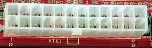
The four extra pins are:
Pin |
Signal |
11 |
+12V |
12 |
NC |
23 |
+5V |
24 |
GND |
Back Panel
The back panel provides the following connectors:
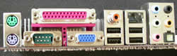
From left to right and top to bottom we have the mouse and keyboard PS/2 female connectors, the Serial and Parallel Port and the VGA connector for the on-board GPU. Then there's the S/PDIF Out-Coaxial for audio output to your speakers, two USB 2.0 ports, the LAN RJ-45 Jack and another set of USB ports. The remaining jacks concern Realtek's onboard soundcard. The first three audio jacks are for 2-channel mode for stereo output and the right two for 7.1 channel audio operation. Last but not least the S/PDIF Out Optical connector for digital sound output.
 |
| The realtek chip responsible for the board's Gigabit LAN interface.. |
Connectors
Below you can see the hard drive connectors. 3 IDE channels and 4 SATA connectors gives you the ability to install up to 10 drives on this motherboard!
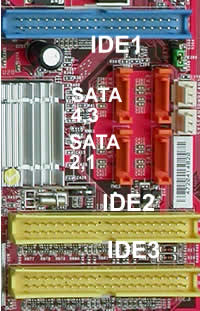
The first primary drive should always be connected to the blue connector: IDE1. The IDE controller behind the blue connector is located on the ICH6R chipset whereas the yellow ones are supported by VIA's 6410 IDE Raid Controller which can connect up to four Ultra ATA 133 drives and also provides RAID 0 & RAID 1 support.
Slots
The 915G Combo mainboard provides one PCI Express 16x slot, two PCI Express 1x slots and three 32-bit PCI bus slots as shown below.

The only 16x PCI-E slot (not to be confused with PCI-X) is only made for graphics card expansion supporting a transfer rate of 2.5GB/s. The PCI Express 1x slots are for next generation peripherals (such as modems, TV tuners etc.) and support maximum transfer rate of 250MB/s.
The three remaining slots might seem familiar as they are plain PCI.
However, the orange one stands out as it supports 2 masters. That means, if the card you install on it supports it (such as a Wireless LAN card), it can act as a communication slot.