DVD Technical Guide
4. Design Concept of the Physical Specification
Review Pages
2. Concepts and Structure of the DVD Format
3. The Future of DVD
4. Design Concept of the Physical Specification
5. Features of the DVD Physical Specification
6. The DVD Data Format
7. Read-Only Disc File Format
8. Video Format
9. Video Format - Page 2
10. Video Format - Page 3
11. Audio Format
12. Audio Format - Page 2
13. Audio Format - Page 3
14. Audio Format - Page 4
15. Audio Format - Page 5
16. DVD-R and DVD-RW
17. DVD-R and DVD-RW - Page 2
18. DVD-R and DVD-RW - Page 3
19. DVD-R and DVD-RW - Page 4
20. DVD-RAM
21. DVD-RAM - Page 2
22. DVD-RAM - Page 3
23. DVD-RAM - Page 4
Chapter 2 - Physical Format of Read-Only Discs
2.1 Design Concept of the Physical Specification
2.1.1 DVD design target
The basic design of the DVD began with the goal of media for movies as content. Therefore, a basic goal was for a playback time of about 133 minutes, which is long enough to allow most movies to fit on a single disc.
However, since DVD was intended as a technology to replace LaserDisc (LD), DVD needed to provide at least equivalent video quality. As the result of many rounds of video quality evaluation, and with the assumption that DVD would use variable-rate video compression, it was determined that a data rate of 3.5 Mbps was the minimum requirement. Then, considering audio quality, flexibility for international use, and multimedia capability, it was decided to provide capacity for Dolby AC-3 audio in three languages (384 kbps x 3) and subtitles in four languages (10 kbps x 4), resulting in the design of a specification which required a disc capacity of 4.7 GB.
The difference between the DVD specification and the CD specification is not just the move from a near-infrared laser to a red laser; the difference is that the entire specification is designed to achieve a disc capacity of 4.7 GB, based on the evolution in technology in the ten-plus years since the CD was introduced in 1982. For instance, requirements for parameters such as disc eccentricity (radial run-out) and tilt have become considerably more strict than in the CD specification. This recognizes evolution in disc manufacturing technology, as well as the fact that the recording density has increase proportionally more than the laser wavelength decreased, reducing total system margin.
For example, the standard CD track pitch is 1.6 microns. Reducing this by the ratio of DVD to CD laser wavelength (650/780) would result in a 1.33 micron track pitch. However, DVD actually requires a track pitch of 0.74 microns, meaning that tracks are considerably more packed than one might expect. As the track pitch decreases, crosstalk increases, and the radial tilt margin is severely reduced. In order to achieve the required density the average track pitch variation was tightened to ![]() 0.01 microns. To reduce crosstalk the maximum allowed variation was also tightened to
0.01 microns. To reduce crosstalk the maximum allowed variation was also tightened to ![]() 0.03 microns.
0.03 microns.
To satisfy this specification, of course, it is necessary for the disc mastering equipment to be sufficiently precise, and the variability in playback device mechanisms and pickups must also be more tightly controlled than in CD players.
The specification known as DVD Book Part 1 describes the physical characteristics of a ROM disc needed to achieve such a system design. That is, the specification describes such things as the required disc mechanical properties, optical properties, and properties of the signal generated upon playback, as well as things like the modulation methods and error correction required to design DVD hardware. The DVD specification also allows dual layer discs and small (![]() 8 cm) discs; these definitions are also contained within this specification.
8 cm) discs; these definitions are also contained within this specification.
Note:
This information is based on DVD Specifications for Read-Only Disc: Part 1 PHYSICAL SPECIFICATIONS, version 1.03. Disc and equipment designers should refer to the most recent versions of the relevant specifications. Pioneer makes no warranty concerning the accuracy of information presented in this article, and is not liable for any damages suffered as a result of any inaccuracies contained herein.
Simply put, the difference between a 4.7 GB DVD and a CD is in the recording density. Below are electron microscope photographs of features called "pits" recorded on CD and DVD media.

From these photos, it is easy to see how much smaller the DVD pits are. The problem is how to record and play back the information from these tiny pits.
CD and LD cutting is done with a mastering machine called a Laser Beam Recorder (LBR). These machines use light sources consisting of argon lasers with 457 nm wavelengths, or helium-cadmium lasers with wavelengths of 442 nm. To increase the recording density for DVD discs, LBRs have been developed which use argon or krypton lasers with near-ultraviolet wavelengths of 351 nm.
 For playback, DVDs require a more tightly concentrated light than CDs do. The playback beam size is proportional to
 ![]() /NA, so DVD players need the numerical aperture (NA) to be large and the wavelength (
/NA, so DVD players need the numerical aperture (NA) to be large and the wavelength (![]() ) to be small in order to realize the tiny playback beam necessary. However, a problem arises when the disc is inclined, or tilted, with respect to the light source. A tilted disc surface cause an optical degradation known as coma aberration, which causes the light spot to be distorted and interferes with correct playback. The degree of coma aberration is proportional to d x NA3/
) to be small in order to realize the tiny playback beam necessary. However, a problem arises when the disc is inclined, or tilted, with respect to the light source. A tilted disc surface cause an optical degradation known as coma aberration, which causes the light spot to be distorted and interferes with correct playback. The degree of coma aberration is proportional to d x NA3/![]() , where d is the disc substrate thickness. DVDs use a substrate that is 0.6 mm thick, compared to 1.2 mm used in CDs, thus reducing the effect of this degradation due to disc tilt by a factor of 2.
, where d is the disc substrate thickness. DVDs use a substrate that is 0.6 mm thick, compared to 1.2 mm used in CDs, thus reducing the effect of this degradation due to disc tilt by a factor of 2.
The figure above shows the relationship of disc tilt to coma aberration.
A 0.6 mm substrate is not physically strong enough, and so it is necessary to bond two 0.6 mm substrates together to form a 1.2 mm substrate. This adds a bonding step in addition to the steps that are required to form the 1.2 mm substrate used in CD media. This extra step tends to increase substrate cost. However, since the substrate is thinner, the cooling time needed in injection molding is shorter. This reduces the cycle time required between injecting the disc material and removing the formed disc. Since a large percentage of the disc cost is the amortization of the manufacturing equipment, the shorter cycle time makes up for the addition of the bonding step, allowing a DVD to be produced for about the same cost as a high-density 1.2 mm substrate.
Further, the DVD specification provides for dual layer discs, which are extremely well-suited to this bonding process, which in turn leads to additional added value.
The next issue that arises is compatibility with CDs. CDs use 1.2 mm substrates while DVDs use 0.6 mm substrates, and the pickup must account for the difference in spherical aberration resulting from this difference in thickness. This can be accomplished using devices which have already been announced, such as dual-focus pickups, dual-lens pickups, or pickups which use liquid crystal devices to provide variable apertures.
Finally, 0.6 mm substrates are at a disadvantage when it comes to surface dirt and damage. Since the pickup beam diameter at the disc surface is only one-half that of the diameter for the 1.2 mm substrate, the DVD pickup is twice as sensitive to surface dirt and damage. This disadvantage is compensated for by using powerful error correction schemes. The CD format provides correction for error bursts up to 2.29 mm long, while the DVD format can correct for error bursts as long as 6.0 mm & more than twice as long. And when it comes to scratches, the CD information layer is covered only by protective lacquer and the printed surface, making the information layer quite vulnerable to scratches on the label side. The DVD, on the other hand, is actually composed of two bonded substrates. Since the information layer is protected by a full 0.6 mm substrate, it is much less vulnerable to label-side scratches than a CD.

The DVD design target is that when the worst-case disc allowed by the specification, considering the economics of production, is played using the worst-case pickup that can be produced in volume economically, the byte error rate after error correction will still be 1 x 10--20, which is good enough to be acceptable for computer applications.
Since the above target is for "after error correction," the error correction capability must be calculated. Considering the tradeoff between error correction capability and the overhead of the added redundancy, the DVD format was set to one ECC block per 32 kB. This requires a byte error rate before correction of 1 x 10⁻².
In order to achieve good economy on both the part of the discs and the playback mechanisms, and many experiments were performed. The current disc tilt specification was determined as a result of the efforts on both sides.
As will be explained hereafter, it is difficult to make the error rate a specification of the disc itself. Therefore, a jitter standard is set by the DVD specifications. A simple calculation based on a normal distribution requires that the jitter rate be under 15.4%, and experimental results indicate that jitter must be under 16%, to achieve the required error rate. Since the disc tilt varies within a revolution, it was decided to adopt the design concept that jitter must remain within 16% at the instantaneous peak value of tilt. Since it is actually very difficult to measure the peak value, the concept became to measure the average jitter at under 15%, and the byte error rate at under 5 x 10⁻³.
The basic concept of system margin is shown in the figure below. In the figure the horizontal axis indicates tilt, while the vertical axis represents jitter.
First, let's consider the best results obtained from many experiments. If there is no tilt, then the jitter value includes components from light source noise, circuit noise, disc noise, standard interference between symbols (inter -symbol interference), and some small amount of crosstalk from the neighboring tracks.
Next, let's find the minimum jitter level due to disc manufacturing variations other than tilt. Experimental results indicate that 8% is a reasonable value, based on the DVD specification.
Next we consider manufacturing variation in the circuitry.
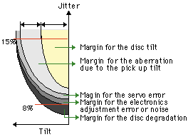 Variation due to the disc and the circuitry have noise-like characteristics, and increase the minimum jitter level, but are thought to have a very small effect on tilt margin. Factors such as offset in the servo circuit, however, both increase the jitter level and decrease tilt margin. The figure shows the components of the reduction in margin, based on experimental results and past volume manufacturing experience. The remaining components are allocated to disc tilt and pickup tilt (including aberrations), resulting in the current specification.
The pits on CDs are typically about ![]() /6 deep. This enables the use of both a push-pull tracking error scheme, which works best at a pit depth of
/6 deep. This enables the use of both a push-pull tracking error scheme, which works best at a pit depth of ![]() /8, and three-beam and differential phase tracking methods, which work best at a pit depth of
/8, and three-beam and differential phase tracking methods, which work best at a pit depth of ![]() /4. In the DVD specification, however, the top priority was to increase recording density, and so the specification was developed assuming the
/4. In the DVD specification, however, the top priority was to increase recording density, and so the specification was developed assuming the ![]() /4 pit depth necessary to obtain optimal signal quality. A push-pull signal is too small to be usable at a
/4 pit depth necessary to obtain optimal signal quality. A push-pull signal is too small to be usable at a ![]() /4 pit depth, but the push-pull scheme has problems with offset due to lens shift and disc tilt anyway, so it was decided that support for that scheme was not important.
/4 pit depth, but the push-pull scheme has problems with offset due to lens shift and disc tilt anyway, so it was decided that support for that scheme was not important.
The differential phase tracking method, however, met all the requirements for compatibility, including handling dual layer discs and different track pitches. Further, this method was felt to be well suited to future recording density increases, and thus it was chosen as the standard tracking method for DVD. The differential phase tracking method does have the weakness of producing an offset in regions where there is strong correlation in bit pattern with the neighboringtracks , but this can be avoided by scramblingthe signal. Dual layer discs
 The DVD specification provides for dual layer discs, in a such a manner that either layer can be played without the need to turn over the disc. This gives rise to problems such as increased spherical aberration due to different substrate thickness when reproducing a signal from the different layers, and a decrease in signal-to-noise ratio due to reflected light from the surface not being played (inter-layer crosstalk). Track density is reduced by about 10% in dual layer DVD discs as a means of increasing margin.
The two layers need to be far enough apart that inter-layer crosstalk is small for standard pickups, but close enough that spherical aberration doesn't become fatal. With this in mind experiments were performed, and the inter-layer distance was specified to be 55 ![]() 15 microns. The substrate thickness specification for dual layer discs was able to be made thin because the thinner the substrate, the easier it is to control coma aberration, thus giving plenty of margin.
15 microns. The substrate thickness specification for dual layer discs was able to be made thin because the thinner the substrate, the easier it is to control coma aberration, thus giving plenty of margin.
Review Pages
2. Concepts and Structure of the DVD Format
3. The Future of DVD
4. Design Concept of the Physical Specification
5. Features of the DVD Physical Specification
6. The DVD Data Format
7. Read-Only Disc File Format
8. Video Format
9. Video Format - Page 2
10. Video Format - Page 3
11. Audio Format
12. Audio Format - Page 2
13. Audio Format - Page 3
14. Audio Format - Page 4
15. Audio Format - Page 5
16. DVD-R and DVD-RW
17. DVD-R and DVD-RW - Page 2
18. DVD-R and DVD-RW - Page 3
19. DVD-R and DVD-RW - Page 4
20. DVD-RAM
21. DVD-RAM - Page 2
22. DVD-RAM - Page 3
23. DVD-RAM - Page 4

