DVD Technical Guide
6. The DVD Data Format
Review Pages
2. Concepts and Structure of the DVD Format
3. The Future of DVD
4. Design Concept of the Physical Specification
5. Features of the DVD Physical Specification
6. The DVD Data Format
7. Read-Only Disc File Format
8. Video Format
9. Video Format - Page 2
10. Video Format - Page 3
11. Audio Format
12. Audio Format - Page 2
13. Audio Format - Page 3
14. Audio Format - Page 4
15. Audio Format - Page 5
16. DVD-R and DVD-RW
17. DVD-R and DVD-RW - Page 2
18. DVD-R and DVD-RW - Page 3
19. DVD-R and DVD-RW - Page 4
20. DVD-RAM
21. DVD-RAM - Page 2
22. DVD-RAM - Page 3
23. DVD-RAM - Page 4
2.3.1 ID, IED, and EDC
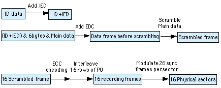
The figure below shows the process used in encoding.
First, two bytes of error correction code are added to a four-byte ID. This is done to enable fast access by making it easy to read the ID using only the ID's error correction code, without having to calculate and check the error correction code which is later added to the entire data block. To this ID is added six bytes of control data, 2048 bytes of main data, and a four-byte EDC code. This EDC code is used for checks such as determining whether scrambling has been performed correctly, and whether error correction has occurred after the error correction code is calculated and checked.
2.3.2 Scrambling
After the EDC is appended, the data is scrambled. This is done to randomize the data and prevent problems like interference from a repeating pattern in the neighboring track, or a repeating pattern in the data resulting in a large DC component which affects the data slicing or servo. Note that the data used in the scrambling process will not have any fixed pattern, but will be comprised of 16 values, based on four bits in the ID, in a manner chosen to also be effective in recording. The initial value is taken from the four bits beginning with the fifth bit from the end of the ID, to provide the same scrambling to 16 sectors of data. Therefore, the scramble pattern makes one complete cycle in 16 x 16 = 256 sectors. This scrambling is done for the purpose of randomizing the data, which is particularly important for differential phase tracking. In differential phase tracking, a proper error signal cannot be generated if the pit arrangement in the adjacent track is in some particular pattern. At the inner circumference of the disc there are about 29 sectors around one complete revolution. Since the same scrambling continues for 16 sectors, the necessary condition has been met at the inside circumference. At the outer circumference there are about 70 sectors in one complete revolution. This is less than a full cycle of 256 sectors, so again the necessary condition has been met. The conditions will still be met a blue laser is used to increase recording density by a factor of 1.5. ECC encoding is done on the scrambled 16 sectors, using product codes.
2.3.3 ECC (Error Correction Code) block and interleaving
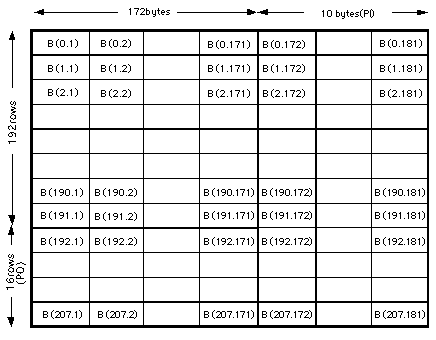
The figure above shows the data in block structure after ECC has been added, with 10 bytes of Reed-Solomon check code (182, 172, 11) added to each row of 172 bytes, and 16 bytes bits of Reed-Solomon check code (208, 192, 17) added to each column of 192 bytes . After the ECC has been added, each of the bottom 16 rows is interleaved with the data so that there are 12 rows of data followed by one row of parity check code, as shown in the figure at right. This block of 13 rows of 182 bytes each comprises one recording frame, before the addition of modulation and synchronization signals.

2.3.4 Sync Code
Each row of a recording frame is divided into two equal parts, and a 32-bit synchronization (SYNC) Code is added to each group of 91 bytes(91 x 16 channel bits= 1456 bits). The pattern of this SYNC Code field is
AAA*******0001000000000000010001
The latter part of this field is a combination of 14T and 4T. The Tmax in the data is 11T, so adding 3T to make a pattern of 14T in the SYNC field means that even if 11T becomes 12T due to an edge shift, and if 14T becomes 13T due to an edge shift, it will still be possible to distinguish them. After the 14T comes a fixed 4T, and with the previous having a gap of at least 4T, it is prevented from having symbol interference with the 14T. The AAA portion is chosen to be either 000, 001, or 100, depending on the relationship with the previous word (defined by the condition and the (d, k) limitation). The seven bits indicated by ******* are used in combination with the three AAA bits to form one of 32 different patterns, and assigned one of two different codes with different edge transition numbers for eight types of SYNC Codes ranging from SY0 through SY7. Utilizing the two codes with different edge transition numbers for each SYNC Code allows look-ahead DC control. (DC control is done by choosing the the one of the two types of SYNC Code which will result in a smaller DSVuntil the point where DC control is next performed.) The figure at right shows the combination of the SYNC Codes for the 13 rows in a sector.
 Each sector begins with SY0, and each row is uniquely identifiable by the pattern of cyclically repeating SY1 through SY4 and SY5 through SY7 codes. Error correction codes are generated over 16 sectors. The ID information following the SY0 at the beginning of the block is read and recognized as an address which is divisible by 16. SY0, that is to say, the beginning of the sector, plays an important role in decoding the data.
Since the individual rows are uniquely identifiable in the sector structure, several rows can be read and the location of a coming SY0 can be calculated from the periodicity of the rows' SYNC Codes. This makes it possible to interpolate and read the next ID, even if for some reason the SY0 code is unreadable. Key features of this sector block structure are the large error correction code block and the ability to determine the sector head even if the actual pattern is unreadable.
The SYNC Codes were defined to realize in just 32 bits the features described above, namely a 14T length SYNC pattern that is 3T longer than the Tmax in the data region, DC control, and the identification of the sector start.
The synchronization frequency of a standard test unit is based on the 27 MHz clock of the video system, and is divided down by (512 x 3) to 17.578125 kHz. Since the channel clock is one SYNC frame interval, or (91 + 2) x 16 = 1488 bits, the channel clock frequency becomes 27 MHz x 1488 / 512 / 3 = 26.15625 MHz.
The ID information added to each sector is comprised of four bytes. The lower-order three bytes contain the sector number. The upper byte provides a bitmap of information which the drive requires in real time, namely the sector format (ROM or RAM), tracking method (pit tracking or groove tracking), reflectivity (greater or less than 40%), disc region (lead-in, lead-out, or middle data), and layer information (layer 0, layer 1, other). Note that the layer information is contained in the lowest-order bits of the byte, putting it in a position to be considered as the upper bits of the sector number.
2.3.5 Lead-in, middle, and lead-out regions
The CD's table of contents information is contained in the lead-in area, and contains a table of information used to access the rest of the disc. The DVD specification, however, adopts the concept that all information about the data content is contained within a file system, and exists within the data itself. Therefore, the information written in the lead-in (middle region) is information necessary only for the drive itself, such as disc compatibility and drive control information. (There are also regions for manufacturer information or related to copying.)
This information is called control data, and is written in the 17.5 to 105 tracks located inside the data region start radius of 24 mm. One block of the control data is an ECC block (16 sectors), and is written across 192 blocks, or in other words, is repeated 192 times. The first sector of the control data contains physical format information. The physical format information describes what type of disc it is, conforming to what revision of the specification. It also describes the disc size, the maximum transfer rate with consideration for portable players, number of layers, track path type, whether the disc is all ROM or partial ROM, recording linear density, track density, and start and end sector numbers.
Starting 16 tracks inside of the control tracks and covering two blocks of length is recorded a reference code used for equalizer calibration. Inside of this, ROM discs also contain a region of all-zero data extending inward to a radius of 22.6 mm.
Review Pages
2. Concepts and Structure of the DVD Format
3. The Future of DVD
4. Design Concept of the Physical Specification
5. Features of the DVD Physical Specification
6. The DVD Data Format
7. Read-Only Disc File Format
8. Video Format
9. Video Format - Page 2
10. Video Format - Page 3
11. Audio Format
12. Audio Format - Page 2
13. Audio Format - Page 3
14. Audio Format - Page 4
15. Audio Format - Page 5
16. DVD-R and DVD-RW
17. DVD-R and DVD-RW - Page 2
18. DVD-R and DVD-RW - Page 3
19. DVD-R and DVD-RW - Page 4
20. DVD-RAM
21. DVD-RAM - Page 2
22. DVD-RAM - Page 3
23. DVD-RAM - Page 4

